Tag Archives: ESP8266

Christmas Lights 2017

Overview

This year (2017), I decided to put up some Christmas lights at home, they consist of basic shop-bought ones and also home made programmable ones.

There will be quite a few different parts to this projects so i’ll separate them into individual posts. Click the links below to access them…

The Pixel Lighting Controllers

Power Supply and Distribution

LED Pixel Grid

LED Pixel Spinner

ESP Pixel Controllers

The Lighting Controllers

I’ll need to build controllers which will take the data from the main PC running the sequencing software (Vixen) and in turn switch on the correct LED’s at the designated values.

My original plan was to use RS485 Serial connection to send the data around to the controllers as i know this is how people have done it in the past, i also have a little experience with RS485 / Serial so there would be less of a learning curve.

After a little bit of research i came to the conclusion that the Serial communication method is a little out-dated and naturally IP / Wireless has become the norm. With the ESP8266 being my personal favorite ‘WiFi enabled’ Micro-controller, a quick google discovered that others had already done exactly what i have set out to achieve with regards to the controller. 

I did a quick search online for an overall diagram of system but couldn’t find anything, so i came up with this..

I came across the ESPixelStick project which is perfect. I’ll be able to upload the firmware to the ESP and then do all the configuration through it’s web interface. The only thing i had to edit in the code was my access point credentials. I highly recommend checking out the ESPixelStick GitHub if you plan on building any ESP based lighting controllers.

Having the software side looking promising i programmed a NodeMCU board with the firmware and wired up a Pixel RGB LED Strip. Configuring the ESP via the web interface was easy enough. But it just wasn’t working. I was getting strange erratic results from the LED strip. A 10K pullup resistor on the data line of the Led strip seemed to fix the issue.

Knowing it was all now working as planned, i drafted up a schematic…

Knowing i was going too need a few of these, i designed a PCB and sent it off to DirtyPCBs to get them made. I was in a bit of a rush to get this done fairly soon as it can take a few weeks to receive them, still great value for money. I managed to squash it into 2.5x5cm so i can fit two of them into the 5x5cm limit board size.

Whilst waiting for the boards to be made, i put a prototype together. This would allow me to program and test the ESP modules in advance.


Only problem is – it didn’t work. After a bit of testing / googling it turns out that the Generic Level Shifters don’t switch fast enough for the data. I haven’t come up with a sleek method to shift the 3.3v up, but i did come across this post on HackADay, which will do the trick. Hopefully i can make a WS2812 fit on the PCB that’s already being manufactured…

In the mean time, connecting it directly to the 3.3v data from the ESP seems to work fine. 

After a few weeks the PCBs arrived…


First thing to note – don’t bother getting white boards! I though white would be cool as it’s a bit different and almost christmasy… Except you can barely see the traces which is actually rather annoying in an test/development situation! I soldered the components on including the WS2812 LED as mentioned in the Hackaday post but it wasn’t working. The individual led worked fine but not the string connected after it. If i added another WS2812 LED that also worked fine. So i can only assume that the WS2812 LEDs and the WS2811 strings are not compatible?

In the end i replaced the 3.3v regulator with 3.6v instead. This is the max rated input voltage for the esp and increases the data line voltage slightly. This seems to work pretty reliably so far.

The next job was to design and print some waterproof enclosures for them you can read about where i got the design in my other post


Xmas Lights Pixel Grid

Outside my home, facing the main road i have some railings, i decided to attach LED pixels to them to form a ‘pixel grid’. Think of it as an extremely low resolution LED TV. It should allow for some fancy patterns and even scrolling text.

So as usual the first thing to do is draft up some sort of design, so i came up with this..

Pixel Grid Design

So the total Pixel dimensions is 13 High x 48 Wide Giving a total of 624 Pixels.

Each pixel requires 3 data ‘channels’ (Red,Green,Blue) meaning a total of 1872 Data channels are needed. As the maximum limit of the ESPixel controllers is 512, I’ve divided the grid into 4, meaning each controller is configured for 156 Pixels (468 Channels).

The next step was to figure out how to power the LEDs and more importantly how to overcome the Voltage drop along the cables. As the strings are only 5V voltage drop is a big issue. I didn’t do any fancy calculations at this point. It was a simple case of ‘inject’ wherever reasonably possible. This is what you can see in the bottom right of the drawing. ‘Start’ is where the controller is connected, and the ‘pwr’s are the parts of the string that are also connected to the 5V supply.

Once i had it all designed, it was a simple case of cutting the strings up and soldering them all together. I had to add lengths of wire to allow them to reach from one column to another, and also add the extra wire in to ‘inject’ the power. All the connections were covered in adhesive lined heat shrink tubing to try and keep waterproof. This was a very boring process that took many hours.


After finishing that and giving them a test, the next job was to actually fit them all to the railings. This was another very tedious job that took many hours. Each Pixel is held on with two cable ties giving a total of 1248 cables ties that had to be fitted and trimmed.

If i do this again next year i will defiantly be making a some sort of bracket system or some other simple quick way to attach them. I got there eventually though, and i’m pretty impressed with how it turned out.

Xmas Lights Power Supply And Distribution

The LED Pixel lights i’ve put up require either 5V or 12V DC at reasonable high currents. To power them i’m using a PC ATX Power supply i got cheap of Ebay. It has a good power output along with built in overload / short circuit protection.

As we are dealing with small voltages, voltage drop along the cables is a concern. So i’m going to put the power supply as close to the lights as possible which will be outside. This also means i can run one small mains flex through the window, instead of trying to fit multiple thicker cables through.

To keep it protected from the elements the power supply is fixed an a generic IP rated enclosure with a bit of silicone. Whilst it has no airflow in the box, i won’t be using it at it’s full rated wattage, plus it’s very cold outside at the moment. Worst case scenario it will just shut its self of if it does get to warm. 

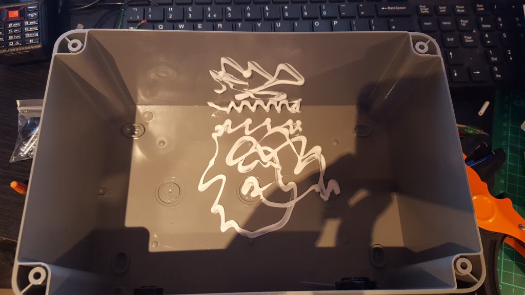
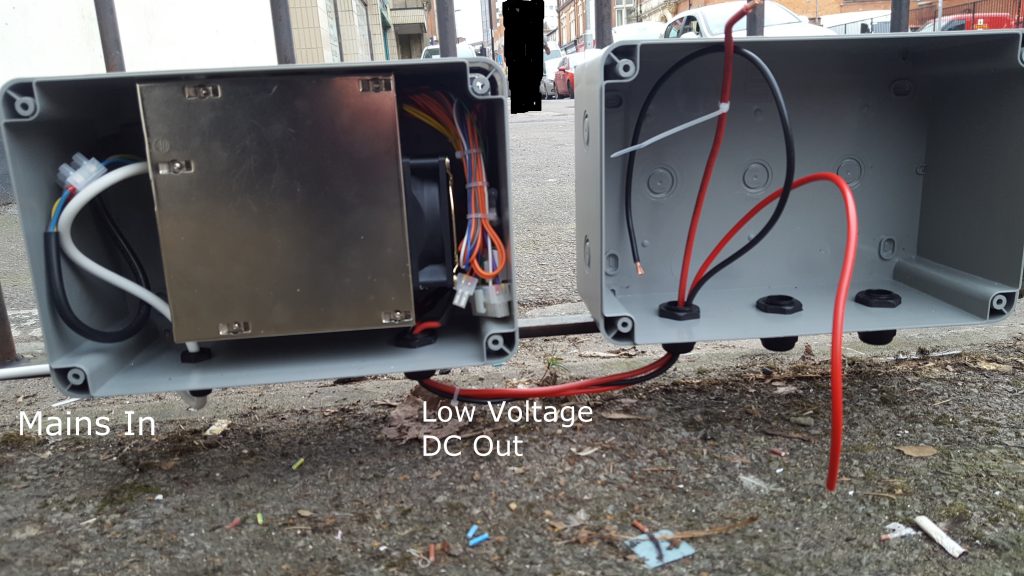
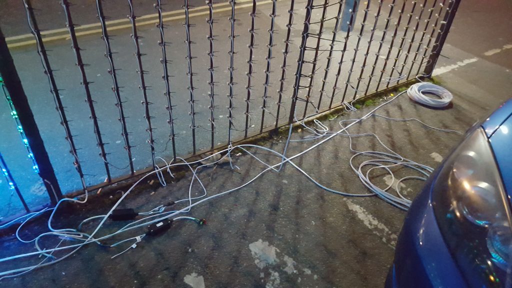
As you can see the box was fitted on my railings next to another. Mains 230v enters on the left and the low voltage DC comes out on the right, into another box. The box on the right is where the Pixel Grid and Pixel Star will be wired into. This keeps the mains nicely separated.

The cable between the two boxes is 4mm that i got from some rubbish jump leads. The cable i used to connect the different elements is 2.5mm Speaker Cable from Ebay. Any thicker cable than this would be allot more expensive and also a struggle to fit through cable glands and into crimps.

Each 1/4 of the Pixel Grid had it’s own 2.5mm supply cable from the power supply.

I 3D Printed junction boxes for making connections in, I found this nice design online and edited it to include another variable to fit a seal, you can find my version here.

I originally tried using an elastic band as a seal but in the end ordered some ‘rubber cord’ from Ebay that does the job well. To test it out i printed a box without holes and then submersed it in shallow water for half hour.

Upon opening the lid i was impressed to see just one tiny drop of water in the corner as you can see above. This means it should be fine when outside in a little rain.

To connect the cables within these junction boxes i used ‘wire nuts’ something that i believe is quite common in the states but not really seen here in the UK. They’re perfect for this as they’re quick and easy whilst still making a good reliable connection. They’re also reusable which is ideal in this temporary situation.

Despite running multiple cables, i still had an issue with the voltage dropping to low and the controllers when all the lights were set to white. This would freeze the micro controller meaning you’d have to reset the power supply to get them going again. As a test, i ran a separate power cable to the controllers on two of the 1/4s and it seemed to solve the issue – something to remember for next year.

I also had the same issue with the Pixel Spinner, to get around it on that one, i changed the supply voltage over to 12V and then used this 12v-5v step down regulator just before the lights.

Whilst advertised as waterproof when i purchased it from Ebay, it clearly wasn’t, so i wrapped it in some Self Amalgamating Waterproof Tape, this should hopefully do the job for a few weeks.