The Lighting Controllers
I’ll need to build controllers which will take the data from the main PC running the sequencing software (Vixen) and in turn switch on the correct LED’s at the designated values.
My original plan was to use RS485 Serial connection to send the data around to the controllers as i know this is how people have done it in the past, i also have a little experience with RS485 / Serial so there would be less of a learning curve.
After a little bit of research i came to the conclusion that the Serial communication method is a little out-dated and naturally IP / Wireless has become the norm. With the ESP8266 being my personal favorite ‘WiFi enabled’ Micro-controller, a quick google discovered that others had already done exactly what i have set out to achieve with regards to the controller.
I did a quick search online for an overall diagram of system but couldn’t find anything, so i came up with this..

I came across the ESPixelStick project which is perfect. I’ll be able to upload the firmware to the ESP and then do all the configuration through it’s web interface. The only thing i had to edit in the code was my access point credentials. I highly recommend checking out the ESPixelStick GitHub if you plan on building any ESP based lighting controllers.
Having the software side looking promising i programmed a NodeMCU board with the firmware and wired up a Pixel RGB LED Strip. Configuring the ESP via the web interface was easy enough. But it just wasn’t working. I was getting strange erratic results from the LED strip. A 10K pullup resistor on the data line of the Led strip seemed to fix the issue.
Knowing it was all now working as planned, i drafted up a schematic…

Knowing i was going too need a few of these, i designed a PCB and sent it off to DirtyPCBs to get them made. I was in a bit of a rush to get this done fairly soon as it can take a few weeks to receive them, still great value for money. I managed to squash it into 2.5x5cm so i can fit two of them into the 5x5cm limit board size.

Whilst waiting for the boards to be made, i put a prototype together. This would allow me to program and test the ESP modules in advance.

Only problem is – it didn’t work. After a bit of testing / googling it turns out that the Generic Level Shifters don’t switch fast enough for the data. I haven’t come up with a sleek method to shift the 3.3v up, but i did come across this post on HackADay, which will do the trick. Hopefully i can make a WS2812 fit on the PCB that’s already being manufactured…
In the mean time, connecting it directly to the 3.3v data from the ESP seems to work fine.
After a few weeks the PCBs arrived…


First thing to note – don’t bother getting white boards! I though white would be cool as it’s a bit different and almost christmasy… Except you can barely see the traces which is actually rather annoying in an test/development situation! I soldered the components on including the WS2812 LED as mentioned in the Hackaday post but it wasn’t working. The individual led worked fine but not the string connected after it. If i added another WS2812 LED that also worked fine. So i can only assume that the WS2812 LEDs and the WS2811 strings are not compatible?
In the end i replaced the 3.3v regulator with 3.6v instead. This is the max rated input voltage for the esp and increases the data line voltage slightly. This seems to work pretty reliably so far.


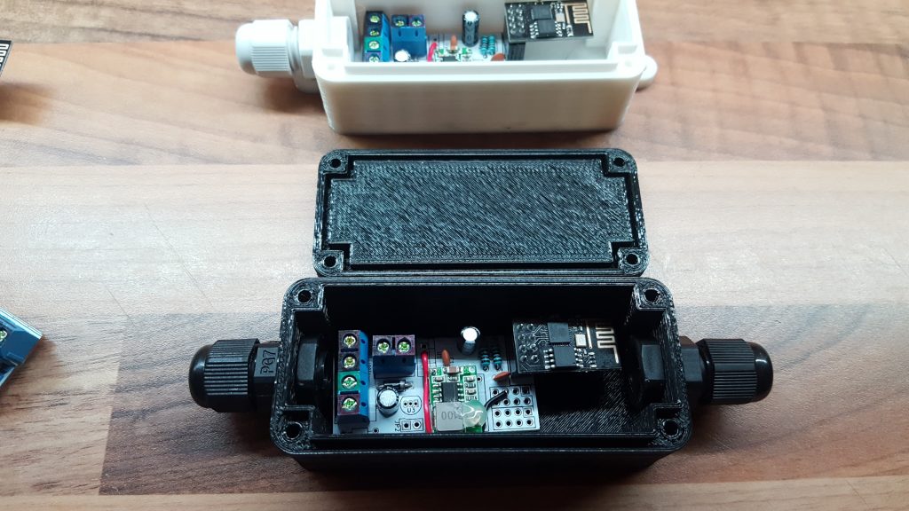
The next job was to design and print some waterproof enclosures for them you can read about where i got the design in my other post.